
Image Source: www.sweetwater.com
Testing: How To Test Impedance Of Speaker Correctly
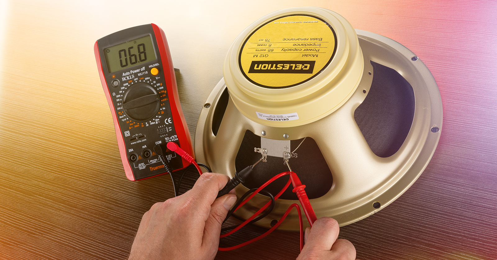
Want to test your speaker’s impedance? You can do this using a multimeter to measure its DC resistance. This DC reading is closely related to the speaker’s nominal impedance, which tells you how much the speaker resists the flow of alternating current (AC) from your amplifier. While a standard multimeter measures DC resistance, which is not the true AC impedance, it gives you a very useful number to check if a speaker is working right and what its approximate impedance is.
Grasping Speaker Impedance
What exactly is speaker impedance? Think of it like resistance to electrical flow. But speakers use alternating current (AC) from your amplifier. Impedance is the total opposition to this AC flow. It includes resistance from the speaker wire and voice coil, plus other factors that change with the sound frequency.
Knowing speaker impedance ohms is very important. It helps you pick the right amplifier. It ensures speaker impedance matching amplifier setups work safely. Speakers have a “nominal impedance” rating, like 4 ohms or 8 ohms. This is a rough average number, but the real impedance changes as the speaker plays different notes.
Connecting speakers with too low impedance to an amplifier can make the amp work too hard and break. Connecting speakers with too high impedance means the amp won’t send out its full power. So, matching impedance is key for good sound and safe equipment.
The Difference: Impedance vs. DC Resistance
This part is important. People often talk about checking speaker “impedance” with a basic meter. But a standard digital multimeter (DMM) measures DC resistance.
DC Resistance (Re): This is the resistance to direct current (DC). It’s a fixed value for the speaker’s voice coil and wires. Your multimeter measures this.
Impedance (Z): This is the opposition to alternating current (AC). It changes with the frequency of the sound signal. It includes the DC resistance plus effects from the coil’s inductance and the speaker’s movement.
So, checking speaker ohms with DMM gives you the DC resistance (Re). This number is always lower than the speaker’s nominal impedance (Z). For most speakers, the DC resistance (Re) is about 70% to 90% of the nominal impedance (Z).
For example, an 8-ohm speaker might have a DC resistance of 5 to 7 ohms. A 4-ohm speaker might measure 2.5 to 3.5 ohms DC resistance measurement. This relationship is why measuring DC resistance is a good way to check a speaker’s state and guess its nominal impedance.
Tools You Need For Testing
You don’t need many tools to check your speaker’s DC resistance. The main tool is something you might already have if you do any electrical work.
Digital Multimeter (DMM)
This is the most common tool for a multimeter speaker test. A DMM can measure voltage, current, and resistance. For speakers, you will use the resistance setting, usually marked with the Greek letter Omega (Ω).
Make sure your DMM works and has good batteries. Some meters are better than others, but a basic one will work for checking resistance and doing a continuity test speaker.
Impedance Meter (Optional but More Accurate)
If you need to know the real impedance at different frequencies, you need a special impedance meter speakers device. These are more expensive and often used by audio pros or speaker builders. They send a specific frequency AC signal to the speaker and measure the response. This gives you the true impedance at that frequency. For simple checks, a DMM is fine.
Test Leads
These wires come with your multimeter. One is usually red (for positive) and one is black (for negative). They have probes on the end to touch the speaker terminals. Make sure they are in good shape and plug into the correct spots on the meter (usually marked “Ω” or “VΩmA” and “COM”).
Pen and Paper (or Phone App)
It’s helpful to write down your readings. This way, you can remember what you measured, especially if you are testing many speakers.
Steps for Multimeter Speaker Test (Measuring DC Resistance)
Here is how to check a speaker using your digital multimeter to get its DC resistance measurement. This process works for testing woofer impedance test, tweeter impedance, or any speaker driver impedance.
Safety First!
Before you start, always do this:
- Turn off all power. If the speaker is part of a system, unplug the amplifier or receiver from the wall. You do not want any power going to the speaker.
- Disconnect the speaker. It’s best to disconnect the wires from the amplifier or receiver going to the speaker. You can test the speaker while it’s still in its box, but the wires connecting it must be free. If testing a loose speaker driver, make sure its wires are not touching anything else.
Prepare the Multimeter
- Turn the meter on.
- Set the dial to resistance. Look for the symbol Ω (Omega).
- Choose the range. Some meters auto-range, meaning they pick the best range themselves. If yours does not, pick a range that covers the speaker’s expected impedance. For typical speakers (4, 8, 16 ohms), a 20Ω or 200Ω range is usually good. If you don’t know, start high and go lower if the reading is “OL” (open line, meaning the resistance is too high for that range).
- Check the leads. Plug the black lead into the “COM” or “COMMON” jack. Plug the red lead into the jack marked “Ω”, “VΩmA”, or “V”.
- Calibrate (Optional but good practice). Touch the tips of the red and black probes together. The meter should read very close to 0 ohms. This checks the leads and the meter itself. If it reads much higher than 0, your leads might be bad or the meter might need new batteries.
Connect Test Leads
Now connect the test leads to the speaker terminals.
- Touch one probe to the positive (+) terminal of the speaker.
- Touch the other probe to the negative (-) terminal of the speaker.
It does not matter which color probe goes on which terminal when measuring resistance. You are just measuring the total resistance of the voice coil wire.
Read the Measurement
Look at the screen on your multimeter. The number you see is the DC resistance (Re) of the speaker’s voice coil in ohms (Ω).
Wait a second or two for the reading to settle. Write this number down.
Interpret the Reading
Okay, you have a number. What does it mean? Remember, this is the DC resistance, not the nominal impedance.
Here’s a general guide for common nominal impedances and their typical DC resistance (Re) ranges:
| Nominal Impedance (Z) | Typical DC Resistance (Re) Range | What the Meter Might Read |
|---|---|---|
| 4 Ohms | 2.5 to 3.5 Ohms | ~2.8 Ω |
| 6 Ohms | 4 to 5.5 Ohms | ~4.5 Ω |
| 8 Ohms | 5 to 7 Ohms | ~6.2 Ω |
| 16 Ohms | 11 to 14 Ohms | ~12.5 Ω |
If your speaker’s DC resistance reading falls within the expected range for its stated nominal impedance, the speaker’s voice coil is likely okay electrically.
- Example: You have a speaker marked “8 Ohms”. You test it and the meter reads 6.1 ohms. This is well within the 5-7 ohm range for an 8-ohm speaker. The speaker’s voice coil is probably fine.
- Example: You have a speaker marked “4 Ohms”. You test it and the meter reads 3.0 ohms. This is in the 2.5-3.5 ohm range for a 4-ohm speaker. Good sign.
- Example: You have a speaker marked “8 Ohms”, but it reads 3.2 ohms. This reading is too low for an 8-ohm speaker but fits a 4-ohm speaker. The speaker might be incorrectly labeled, or there could be an internal issue causing the resistance to be lower than expected (less common).
- Example: You have a speaker marked “8 Ohms”, but it reads 0.5 ohms. This is far too low. It suggests a short circuit, meaning wires inside are touching where they shouldn’t be. The speaker is likely damaged.
- Example: You have a speaker marked “8 Ohms”, but the meter reads “OL” or shows no change from when the leads are apart (infinite resistance). This means the circuit is open. The voice coil wire is broken. The speaker is definitely damaged.
This speaker DC resistance measurement using a DMM is a quick and easy way to check the health of the voice coil and get an idea of the speaker’s impedance class (4 ohm, 8 ohm, etc.).
Performing a Continuity Test Speaker
Most multimeters also have a continuity test function. This is a very simple check to see if there is a complete path for electricity to flow through the voice coil. It’s a quick go/no-go test.
- Set your multimeter to the continuity setting. It often looks like a sound wave symbol or a diode symbol with sound waves.
- Touch the probes together. The meter should make a beeping sound. This shows that the meter is working and a complete circuit is made.
- Connect the leads to the speaker terminals. Touch one probe to each terminal.
- If the meter beeps: This means there is continuity. There is a complete path through the voice coil. The voice coil is likely not broken (open circuit). The meter will usually also show a resistance value (the DC resistance you measured before).
- If the meter does not beep: This means there is no continuity. The path is broken. This points to a damaged voice coil, likely an open circuit. The speaker is probably bad.
The continuity test speaker is a quick way to perform a voice coil impedance test in the sense of checking if the voice coil circuit is complete. It won’t tell you the exact resistance or impedance, but it quickly finds broken voice coils.
Using An Impedance Meter Speakers
While a DMM is great for DC resistance and continuity, using an impedance meter speakers is the proper way to measure true impedance. These meters are designed specifically for audio testing.
How they work: An impedance meter sends a known AC signal at a specific frequency (or sweeps through frequencies) to the speaker. It then measures the voltage and current to calculate the impedance (Z) at that frequency.
Steps for using an impedance meter:
- Safety first! Always disconnect the speaker from the amplifier or any power.
- Connect the meter. Connect the meter’s leads to the speaker terminals. Pay attention to polarity if the meter requires it, though for just measuring impedance, it often doesn’t matter.
- Select the frequency. Some meters let you choose a frequency (like 1kHz, a standard test frequency) or sweep across a range.
- Take the reading. The meter will display the impedance in ohms at the selected frequency. Some meters can graph impedance versus frequency.
Using impedance meter speakers gives you a much more complete picture of how the speaker behaves electrically across the audible range. This is valuable for speaker design, crossover design, and detailed troubleshooting. However, for a simple “is this speaker working?” or “what’s its approximate nominal impedance?” question, the DMM method is usually sufficient.
Interpreting Speaker Test Results
Let’s put the test results together.
-
DC Resistance Reading (from DMM):
- A reading within the typical range (e.g., 5-7 ohms for an 8-ohm speaker): The voice coil is likely okay electrically. The speaker is probably functional in terms of having a complete, correctly resistive coil.
- A reading very close to 0 ohms (e.g., less than 1 ohm): This means a short circuit. Current is flowing with almost no resistance, which is bad. The voice coil is likely damaged by touching wires. The speaker is probably bad.
- A reading of “OL” or infinite resistance: This means an open circuit. The path for current is broken. The voice coil wire is broken somewhere. The speaker is definitely bad.
- A reading that doesn’t match the stated impedance class: The speaker might be mislabeled, or there could be a less common internal issue. Double-check your meter and connections.
-
Continuity Test (from DMM):
- Beep: Continuity is good. The voice coil is not broken.
- No beep: No continuity. The voice coil is broken. Speaker is bad.
-
Impedance Meter Reading:
- This gives you the actual AC impedance at a specific frequency. This is useful for advanced work but not needed for basic checks.
Important Note: These electrical tests (DC resistance, continuity) check the voice coil’s electrical state. They do not check the speaker’s sound quality. A speaker can pass these electrical tests but still sound bad because of mechanical problems (like a damaged cone, a loose dust cap, or the voice coil rubbing). They also don’t test the crossover if the speaker is part of a multi-driver system.
Speaker Impedance Matching Amplifier
Knowing the speaker impedance ohms is crucial for safe use with an amplifier. Amplifiers are designed to work with speakers within a certain impedance range.
- Connecting speakers with too low impedance: This is the most dangerous situation. If an amplifier is rated for 8-ohm speakers and you connect 4-ohm speakers (or lower), the amplifier has to work much harder to push current. This can cause the amplifier to overheat and burn out. Think of trying to run uphill with a heavy weight – it’s much harder work.
- Connecting speakers with too high impedance: If you connect 16-ohm speakers to an amplifier rated for 8 ohms, the amp will deliver less power. The system will play quieter. This isn’t usually harmful to the amplifier, but you won’t get the best performance.
Always check your amplifier’s manual to see the minimum speaker impedance it can safely handle. Common minimums are 4 ohms or 6 ohms.
You can connect multiple speakers to one amplifier output. The way you wire them affects the total impedance the amplifier “sees”.
- Series Wiring: Connect speakers in a chain (amp + to speaker1 +, speaker1 – to speaker2 +, speaker2 – to amp -). The total impedance is the sum of the individual impedances. Two 8-ohm speakers in series make a 16-ohm load.
- Parallel Wiring: Connect speakers side-by-side (amp + to speaker1 + and speaker2 +, amp – to speaker1 – and speaker2 -). For speakers of the same impedance, the total impedance is the individual impedance divided by the number of speakers. Two 8-ohm speakers in parallel make a 4-ohm load. Two 4-ohm speakers in parallel make a 2-ohm load (be careful, many amps can’t handle 2 ohms!). For speakers with different impedances in parallel, the formula is more complex (1/Z_total = 1/Z1 + 1/Z2 + …).
Understanding how to calculate the total impedance helps you safely connect multiple speakers while ensuring proper speaker impedance matching amplifier requirements are met.
Testing Different Speaker Types
The process of checking DC resistance with a multimeter works for almost all types of passive speaker drivers.
Woofer Impedance Test
Testing a woofer is the same as testing any other driver. Disconnect it, set your DMM to ohms, and touch the probes to the terminals. You will get the DC resistance of the woofer’s voice coil. Use the table earlier to see if the reading is normal for the woofer’s stated impedance (usually 4 or 8 ohms for car audio or subwoofers, often 8 ohms for home audio).
Speaker Driver Impedance
This term applies to any individual speaker part: a woofer, a midrange, or a tweeter. To test the impedance of a speaker driver, you test its terminals directly using the multimeter method described. Ensure the driver is disconnected from any crossover or other drivers first for the most accurate reading of that specific driver.
Testing Speaker Systems (Multiple Drivers/Crossover)
If you test the main terminals of a speaker cabinet that contains multiple drivers (woofer, tweeter, etc.) and a crossover network, the reading you get on your multimeter is still the DC resistance seen from the input terminals. This reading will be influenced by the crossover components (coils, capacitors, resistors) as well as the drivers.
This DC reading is less directly related to the speaker’s nominal impedance than when testing a single driver. The nominal impedance of a system is a complex value determined by all components working together across frequencies. The DC resistance measured at the system terminals is useful for checking continuity (a reading near 0 or infinite still indicates a problem) and comparing to a known good speaker of the same model. However, relying solely on the DC reading to confirm the nominal impedance of a complex system can be misleading. Using impedance meter speakers is necessary for true system impedance analysis.
Common Problems & Troubleshooting
When doing a multimeter speaker test, you might get unexpected results. Here’s what they could mean:
- Reading is “OL” or infinite: The circuit is open. The voice coil is broken. This is a common failure.
- Reading is very low (near 0 ohms): There’s a short circuit. Voice coil wires are touching improperly. This can happen if the coil overheats or moves out of place.
- Reading jumps around or is unstable: This could mean a loose connection, either at the speaker terminals, the meter leads, or inside the voice coil itself (like a voice coil rubbing). Check your connections first.
- Meter won’t turn on or shows a strange symbol: Check the meter’s battery. Replace it if needed. Also, make sure the leads are plugged into the correct jacks.
- Reading is way off the expected range but not 0 or infinite: Double-check the speaker’s stated impedance. Ensure your meter is set to the correct range and is working correctly (test the leads by touching them together). If the meter and connections are good, the speaker might have an internal issue or be mislabeled.
Remember, the electrical test only confirms the voice coil’s basic electrical health. It doesn’t mean the speaker sounds perfect or has no mechanical issues.
Benefits of Knowing Speaker Impedance Ohms
Knowing the speaker impedance ohms offers several advantages:
- Proper Amplifier Pairing: The most critical reason. It ensures you connect speakers that your amplifier can handle safely, preventing damage to expensive equipment. This is essential for speaker impedance matching amplifier setups.
- Troubleshooting Speaker Issues: If a speaker isn’t working, checking its DC resistance with a multimeter speaker test is a primary diagnostic step. A reading of 0 or infinite quickly tells you if the voice coil is shorted or open.
- Building or Modifying Speaker Systems: If you are designing your own speaker boxes or systems, knowing the impedance of individual speaker driver impedance helps you design appropriate crossover networks and calculate the total system impedance.
- Buying Used Speakers: A quick check of the DC resistance can help confirm the stated impedance or spot a speaker with a damaged voice coil before you buy.
- Understanding Speaker Specifications: It helps you make sense of technical specs and make informed choices when buying audio gear.
By performing a speaker DC resistance measurement, you gain valuable insight into your speaker’s electrical condition and its suitability for your amplifier.
Frequently Asked Questions (FAQ)
-
Can I test speaker impedance with a multimeter?
You can use a standard multimeter to measure a speaker’s DC resistance (Re), which is related to its impedance (Z). A multimeter does not measure true AC impedance, but the DC resistance is a good indicator of the speaker’s health and approximate impedance class. -
What should an 8-ohm speaker read on a multimeter?
An 8-ohm speaker will typically show a DC resistance reading between 5 and 7 ohms on a multimeter. This is because DC resistance is usually lower than the nominal AC impedance. -
What does infinite resistance mean on a speaker test?
An infinite resistance reading (often shown as “OL” or similar on the meter) means there is an open circuit. This means the voice coil wire is broken, and electricity cannot flow through it. The speaker is likely faulty. -
What does a reading near zero ohms mean?
A reading very close to zero ohms (e.g., under 1 ohm) indicates a short circuit. This means parts of the voice coil or wiring that shouldn’t be touching are making contact. This is also a sign of a damaged speaker. -
Is speaker impedance always the same?
No, the true impedance of a speaker varies with the frequency of the sound signal. The nominal impedance (like 8 ohms) is just an average or rough rating given by the manufacturer.
Testing speaker resistance using a multimeter is a simple yet powerful way to check the basic health of your speaker drivers and help ensure you match them correctly with your amplifier. While it doesn’t measure true impedance, the DC resistance reading provides crucial information for troubleshooting and system building.